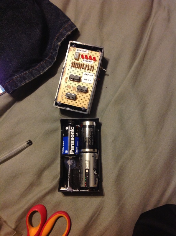
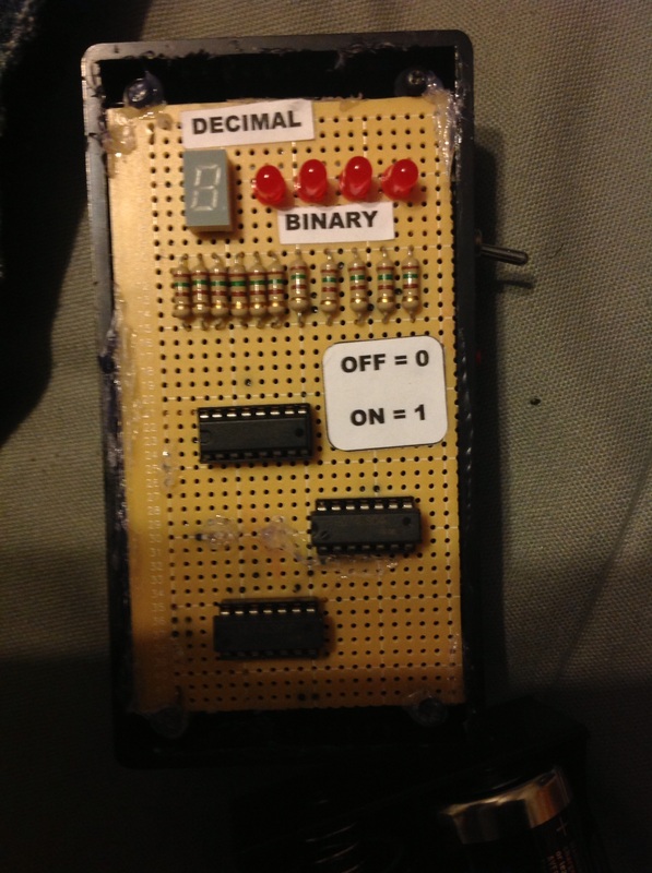
Digital Counter Circuit
The Digital Counter Circuit is an electronic project that converts digital numbers (0-9) to binary (0-1). If you want to understand binary code, please click on "Binary Code PPT" to view a PowerPoint on Binary Code. Below is the Parts List, Schematic, and other information on how to build it. It will cost somewhere between $20 & $30 depending on tax and shipping. I bought all the parts from Jameco Electronics and RadioShack.
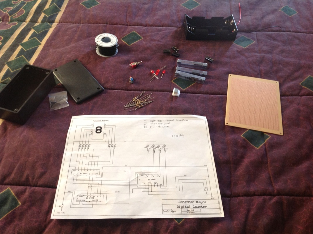
PARTS LIST:
Jameco Electronics:
RadioShack:
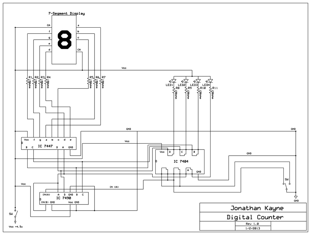
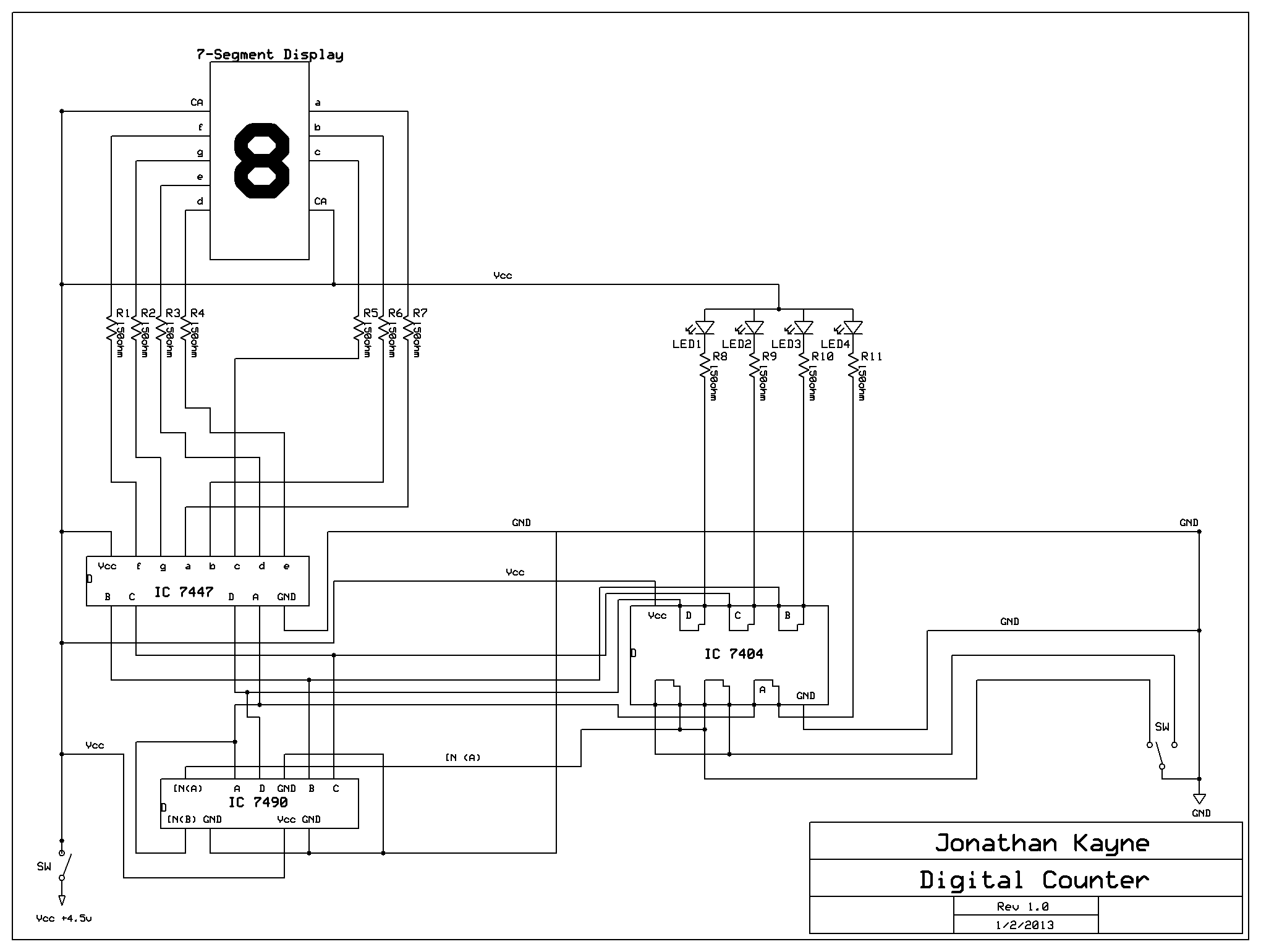
CLICK HERE TO DOWNLOAD THE SCHEMATIC YOUTUBE LINK https://www.youtube.com/watch?v=lcg1iWp1d8Y
If you want to get any of the parts, click on the item number to go purchase it from the manufacturer. To build this, it will take a lot of patience and a steady arm and will involve soldering. When soldering the wires to the pins, first solder the pins to the perfboard then put the tip of the wire against the pad while the solder is still melted. Hold the wire down until the solder cools. If you have a 3 way connection, make a solder-bridge between the connections. Most of these are from the 4 Binary Code lines (A, B, C, D) between the 3 IC's. I recommend that you find a spot on the perfboard, solder each of the 3 wires down to 3 adjacent pads, & solder-bridge them together. On the IC 7404, 4 of the pins are used to prevent a "bounce" effect from happening. To do this, you make a RS NOR latch by connecting the 2 inverters in series (the output of one is connected to the input of another.)
TIPS:
PARTS LIST:
Jameco Electronics:
- IC 74LS47 - Binary to 7 Segment Display Decoder #47790 $1.49
- IC 74LS04 - Hex Inverter #46316 $0.49
- IC 74LS90 - Binary Counter #48119 $1.75
- Single-Pole, Single-Throw (SPST) Toggle Switch #76523 $1.49
- Single-Pole, Double-Throw (SPDT) On-On Push Button Switch #72645 $0.99 (Sale price)
- 10-pack - Red LED (only 4 is needed) #333973 $0.12 ea
- 7 Segment Display (Common-Anode) #2129713 $0.75
- 4.5V Battery Holder (You can get a 4 compartment battery holder and solder a wire to 2 ends on 1 compartment to make it hold 3 batteries. I used a 4-D Cell holder and soldered and glued a nail to 1 end) #216401 $1.35
- 22AWG Wire (100 feet) #36792 $7.95
- (Optional) Project Enclosure (4.875" x 2.5") #18914 $3.95
RadioShack:
- (3x) 5-pack 150 ohm 1/2W Carbon-Film Resistors (only 11 are needed) #271-1109 $1.19 x 3 = $3.57
- (Optional) (2 pack) 16 pin IC socket (only 1 is needed) #276-1998 $0.99
- (Optional) (2x) (2 pack) 14 pin IC socket (only 3 are needed) #276-1999 $0.99 x 2 = $1.98
CLICK HERE TO DOWNLOAD THE SCHEMATIC YOUTUBE LINK https://www.youtube.com/watch?v=lcg1iWp1d8Y
If you want to get any of the parts, click on the item number to go purchase it from the manufacturer. To build this, it will take a lot of patience and a steady arm and will involve soldering. When soldering the wires to the pins, first solder the pins to the perfboard then put the tip of the wire against the pad while the solder is still melted. Hold the wire down until the solder cools. If you have a 3 way connection, make a solder-bridge between the connections. Most of these are from the 4 Binary Code lines (A, B, C, D) between the 3 IC's. I recommend that you find a spot on the perfboard, solder each of the 3 wires down to 3 adjacent pads, & solder-bridge them together. On the IC 7404, 4 of the pins are used to prevent a "bounce" effect from happening. To do this, you make a RS NOR latch by connecting the 2 inverters in series (the output of one is connected to the input of another.)
TIPS:
- Vcc is Positive (+)
- GND is Negative (-)
- All the Cathodes (-) must have a resistor
- To prevent the wires from crossing each other accidentally, use some liquid electrical tape to insulate the wires
